Stream line based techniques rely on tracing a path through the field starting at some point in the field. Once the path has been traced, the path is represented using geometric primitives. When visualizing 3-dimensional fields, illumination and shading provide additional visual cues, particularly for dense collections of stream lines. One type of geometry that can be used is tube shaped geometry constructed from segments of cylinders following the path. In order to capture accurate shading information the radius of the cylinders needs to be finely tessellated resulting in a large polygon load when displaying a large number of stream lines.
Another possibility it to use line primitives since they can be rendered very efficiently and allow very large numbers of streamlines to be drawn. A disadvantage is that lines are rendered as flat geometry with a single normal at each end point so they result in much lower shading accuracy compared to using tessellated cylinders. In [95] an algorithm is described to approximate cylinder-like lighting using texture mapping.
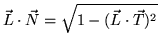
The main idea behind the algorithm is to choose a normal
vector that lies in the same plane as that formed by
the tangent vector ![]() and light vector
and light vector ![]() .
The diffuse and specular lighting contributions are then
expressed in terms of the line's tangent vector and the light vector
rather than a normal vector. For the diffuse term,
.
The diffuse and specular lighting contributions are then
expressed in terms of the line's tangent vector and the light vector
rather than a normal vector. For the diffuse term,
 .
This allows the diffuse cosine term to be evaluated using
the OpenGL texture matrix to compute
.
This allows the diffuse cosine term to be evaluated using
the OpenGL texture matrix to compute
![]() , by
specifying the components of the tangent vector in
the texture coordinate and the components of the light vector
in the texture matrix,
, by
specifying the components of the tangent vector in
the texture coordinate and the components of the light vector
in the texture matrix,
The resulting ![]() texture coordinate is
texture coordinate is
![]() which has been biased to
ensure that the computed coordinate value lies in the
range
which has been biased to
ensure that the computed coordinate value lies in the
range ![]() .
The
.
The ![]() texture coordinate is then used to index a 1-dimensional
texture storing the cosine function modulated
by the material diffuse reflectance
texture coordinate is then used to index a 1-dimensional
texture storing the cosine function modulated
by the material diffuse reflectance
![]() .
.
Similarly the specular term
![]() can be expressed in
terms of the tangent vector and viewing direction
can be expressed in
terms of the tangent vector and viewing direction ![]() as
as
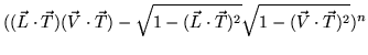 .
Using the texture matrix,
.
Using the texture matrix,
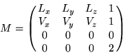
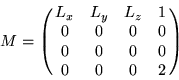
Since the texture map encodes the material reflectance coefficients, multiple texture maps are required for multiple materials. This need for multiple maps can be eliminated by sending the material color as the line color and storing only the light intensity in the texture map. The two can be combined using the GL_ MODULATE texture environment function. Multiple maps or recomputations are required to support different combinations of diffuse and specular properties.
The illuminated lines can also be rendered using transparency techniques. This is useful for dense collections of stream lines. The opacity value is sent with the line color and the lines must be sorted from back to front to be rendered correctly as described in Section 12.